Solving Complex Staging and Rigging Problems with Care
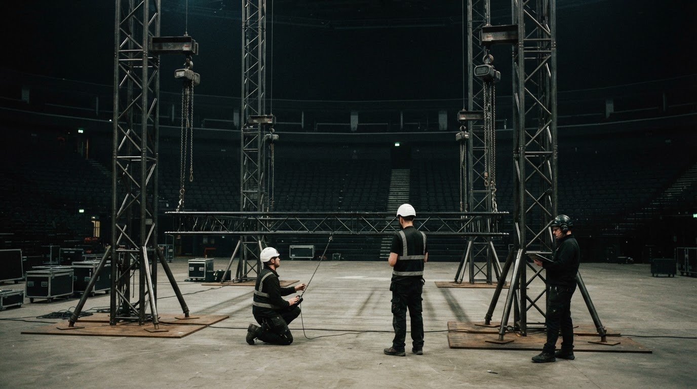
A complex lift is only as reliable as the plan behind it. Solving complex staging and rigging problems starts with understanding the load, checking the venue’s structure and floor capacity, and coordinating every part of the lift before equipment moves.
That preparation matters when deadlines are tight and multiple teams, structures and systems must work together. A clear plan identifies constraints early, defines responsibilities and reduces avoidable disruption during setup and takedown.
This article explains how to assess equipment weight and load distribution, coordinate lift teams, evaluate venue conditions and plan ground-supported rigging where permanent points aren’t suitable. It also covers transport routes, modular systems, installation and removal, showing how each decision fits into a controlled production plan.
Key Takeaways
• Start with the full load picture: equipment weight, how it is distributed, lift points and clearance all affect the rigging plan.
• Give every lift a clear sequence, assigned responsibilities and a shared communication plan.
• Assess the venue’s structure, floor capacity and load paths before deciding how staging will be supported.
• Where permanent rigging points are unavailable, a freestanding ground-supported system can provide an alternative, subject to the site and production requirements.
• Plan transport routes, modular assembly, setup and takedown together to keep the production schedule coordinated.
1. Assessing equipment weight distribution and rigging requirements
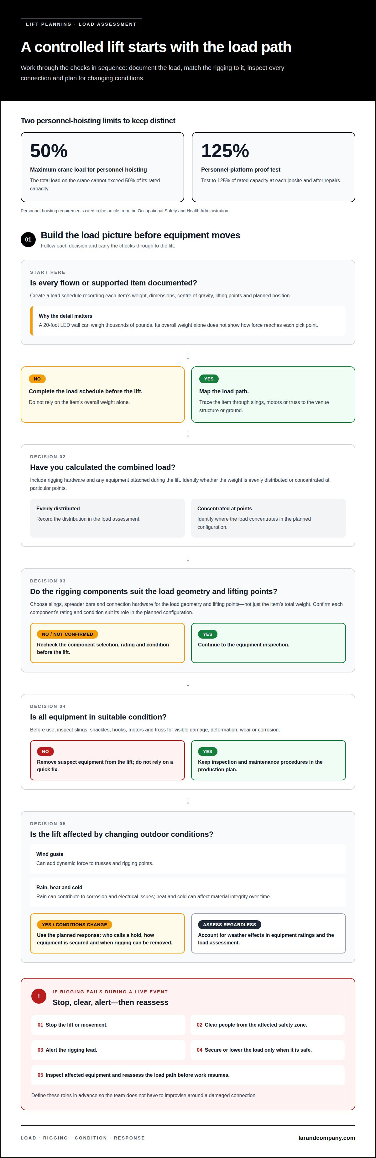
Begin with a load schedule for every flown or supported item. Record its weight, dimensions, centre of gravity, lifting points and planned position. A 20-foot LED wall can weigh thousands of pounds, so its overall weight alone doesn’t show how force reaches each pick point. Map the load path from the item through slings, motors or truss to the venue structure or ground.
Next, calculate the combined load, including rigging hardware and any equipment attached during the lift. Identify whether the weight is evenly distributed or concentrated at particular points. Choose slings, spreader bars and connection hardware to suit the load geometry and lifting points, not just the item’s total weight. Confirm that each component’s rating and condition suit its role in the planned configuration.
For personnel hoisting, the total load on the crane cannot exceed 50% of its rated capacity, according to the Occupational Safety and Health Administration. Personnel platforms must undergo proof testing to 125% of their rated capacity at each jobsite and after repairs, according to the Occupational Safety and Health Administration. OSHA regulation 29 CFR 1926.251 sets requirements for rigging equipment used in material handling on construction sites, according to the Occupational Safety and Health Administration.
Equipment condition matters at every connection. Before use, inspect slings, shackles, hooks, motors and truss for visible damage, deformation, wear or corrosion. Build inspection and maintenance procedures into the production plan, and remove suspect equipment from the lift rather than relying on a quick fix. Rushing a lift, reducing the crew or skipping load calculations can increase the risk of accidents, equipment damage and downtime.
Outdoor conditions can change the load on a rigging system. Wind gusts add dynamic force to trusses and rigging points, while rain can contribute to corrosion and electrical issues. Heat and cold can affect material integrity over time. Set out a clear response to changing conditions: who calls a hold, how equipment is secured and when rigging can be removed. Account for weather effects in equipment ratings and the load assessment.
If rigging fails during a live event, stop the lift or movement, clear people from the affected safety zone and alert the rigging lead. The team should secure or lower the load only when it is safe, then inspect the affected equipment and reassess the load path before work resumes. Define these roles in advance so no one has to improvise around a damaged connection.
2. Communication and coordination during complex lifts
A complex lift requires clear authority as well as sound calculations. Before work begins, the production lead and rigging lead should agree who controls each instruction, who can call a stop and how changes are communicated to every crew. A named lift lead can coordinate the sequence, while the rigging team confirms when the area is clear and ready. This prevents conflicting directions reaching operators during overhead work. The plan should specify radio channels, hand signals, call-outs and what to do if communication fails. Everyone involved needs to understand the same sequence before work starts.
Coordination between departments matters because grip, electric and art teams can affect the same space. Grip may move stands or camera tracks through the lift zone; electric may route cables near motors or truss; art may need to install scenic pieces beneath overhead elements. The production plan should map these interfaces and set the order of work. For example, electric can confirm cable routes before the rigging crew raises equipment, while art can wait to install scenery until overhead work is complete. This reduces clashes, keeps access routes open and helps each department work safely.
Contractors also need a shared schedule. A machinery move may involve transport, electrical work, millwright services, rigging and installation, with each task affecting the next. The coordinator should map dependencies, access requirements and handover points, then share the current schedule with every lead. If a delivery is delayed, the team can identify which work can continue and which tasks must pause. Make updates specific: name the affected area, the change, the responsible lead and the revised sequence. A shared schedule prevents teams from working to different assumptions.
Experienced rigging teams bring practical knowledge of lift sequencing, site constraints and communication under pressure. Give them current drawings, the production schedule, venue rules and details of other contractors’ work. During the lift, the operator should receive clear signals from the designated signal person, not several people at once. The lift lead should monitor progress and stop work if the agreed sequence changes or the work area becomes occupied. A pre-lift briefing can walk through each movement, confirm roles and explain how the team will pause and reset. This structure supports controlled execution without rushing the crew.
Equipment relocation can involve multiple contractors for transportation, electrical work, millwright services, rigging and installation. Keep these work areas in the shared coordination plan, with a schedule that reflects the full range of contractors involved.
3. Venue floor load capacity and structural assessment
A venue’s floor and structure shape where stage elements can safely sit. The assessment should map the planned layout against the building’s available capacity, access routes and support points. Consider the combined weight of stage surfaces, scenery, lighting supports and equipment, then identify where loads concentrate. A distributed load across a broad base affects the floor differently from a heavy point load on a small footprint. Engineers should calculate safe load distribution across temporary supports and monitor each rigging load path. For solving complex staging and rigging problems, this structural picture connects design choices to the building’s actual constraints.
Dimensions are part of that calculation, not a separate design detail. A small corporate presentation stage may measure 24 feet wide by 12 feet deep, but its required capacity depends on what it carries and where that weight lands. For broader technical coordination, working through an event production checklist such as the guidance on debut-media.com helps verify that all essential AV equipment is accounted for alongside the staging. Mark the position of stage legs, towers, scenic elements and equipment on the floor plan. Compare these points with the venue’s structural information, and account for any changes to the layout before load-in. If added equipment increases the load, the structure may need reinforcement before installation proceeds.
Measure equipment weight accurately and use a suitable scale for the load. Professional crane scales can have accuracy levels between ±0.1% and ±0.5% of their capacity. For smaller loads, high-accuracy scales used in fields such as aerospace or pharmaceuticals can measure with better than ±0.05% accuracy. Record the scale reading with the equipment inventory, then use those weights to calculate the load on each support point. Avoid relying on estimates where a measured weight is available.
Plan load-in so equipment reaches its final position without blocking crew access or creating unexpected load concentrations. Show delivery paths, temporary holding areas and the assembly order for stage sections. A trolley or pallet can create a different floor load from the same equipment placed on distributed stage supports. Keep access routes clear and update the floor plan if a delivery route or staging position changes. This helps the installation progress smoothly.
Bring in a structural engineer when the venue’s capacity, support structure or proposed load path needs technical assessment, especially if the plan adds temporary supports or weight. Involve an experienced rigger when lift points, rigging loads or the installation sequence need specialist assessment. A structural assessment is central to solving complex staging and rigging problems when a design adds loads or changes how forces reach the venue. The engineer evaluates structural capacity and distribution; the rigger focuses on the rigging arrangement and lift execution.
4. Freestanding ground-supported stage rigging
Stadiums and outdoor spaces often lack permanent rigging points, so productions may use temporary ground support. The structure transfers loads through its legs and base to the surface rather than relying on the venue roof. Before choosing a system, establish its footprint, intended equipment positions and ground conditions. The support plan must account for the complete structure and attached equipment, not just the visible stage elements.
A 40-foot LED wall is one example of a design that may use ground support. Its size affects the structure’s layout, the space needed behind or beside it, and the route for assembling panels. Set out the wall position and support footprint on the site plan. Keep the resulting structure clear of exits and emergency routes, and coordinate its location with audience sightlines, performers and other production areas.
Ground-supported LED walls and flown arrays address different site conditions. A flown array depends on suitable overhead rigging points and a load path through the venue structure. A freestanding system brings support down to ground level, which can suit a stadium or festival site without permanent points. The choice depends on venue conditions, equipment arrangement and production layout. Don’t assume a flown design can be transferred to ground support without revising its structure and load assessment.
Assess the surface beneath each support leg before assembly. The team needs to know whether the ground is level, firm and suitable for the planned load distribution. Mark leg positions and keep them consistent with the approved layout. If the site surface or position changes, reassess the arrangement before adding equipment. A ground plan should also account for assembly access, nearby structures and the crew’s installation routes.
Temporary systems can combine trussing, lighting supports and stage surfaces in one coordinated layout. Show each element on the production drawings, including connection points and crew access. Set an installation sequence that places the base and supporting structure before heavier production elements are attached. Control the work area while overhead components are assembled, and maintain clear communication between the ground crew and those working above.
For a successful installation, the stage plan, ground support layout and equipment schedule must align. Check that the finished structure fits the site footprint and leaves emergency routes and essential access clear. The crew should follow the planned order for loading, securing and removing components. During takedown, reverse the sequence in a controlled way: remove attached equipment before dismantling the supporting structure. Include the ground system in the production plan from initial layout through removal.
5. Transport, modular systems, setup, and takedown
Common staging and rigging challenges include restricted transport routes, limited access, tight setup windows and equipment that doesn’t fit the original layout. A venue or schedule change can affect several connected tasks. Plan transport, assembly and removal as one integrated operation, with a named lead tracking dependencies between deliveries, site access and crew activity.
Start with the route from the unloading point to the final position. Map access points, floor capacity, turning space, overhead obstructions and utility disconnections before equipment moves. For machinery relocation, also account for final placement, anchoring and access to utilities. This helps crews identify where modular components can be unloaded and assembled before transport arrives.
Modular rigging systems can be configured for different production footprints, but each arrangement needs a defined plan. One studio ceiling rig used an outer freestanding structure measuring 20 by 30 feet with 9-inch Modulus X truss. Its inner truss box measured 16 by 24 feet and used 6-inch Modulus X truss. This example shows how larger and smaller truss sections can form distinct parts of one structure. The design still needs to account for component connections, support positions and the equipment each section carries.
Set clear protocols for receiving, assembling and checking each module. Keep components organised by their position in the build sequence, and make drawings available to the crews handling each stage. For a large production, the rigging team may arrive 24 to 48 hours before the event starts. Use that time to resolve access conflicts, stage components near their intended locations and coordinate work with other departments. A late change to the footprint should trigger a review of the transport route and assembly sequence.
Plan takedown as carefully as installation. Identify what must be disconnected or removed first, where modules will be lowered and how they will return to the loading area. In the studio example, the ceiling rig was built in one day and operational by lunchtime. After the shoot, the structure was rolled out, lowered and de-rigged in roughly an hour and a half. These timings illustrate the value of a sequenced plan, not a promise for every site.
For productions with complex transport, modular assembly and removal requirements, discuss your production logistics.
Lar&Co
Lar&Co helps bring complex live productions together when staging, rigging, venue constraints and tight schedules call for coordinated decisions. Through Show Production, Technical Production and Site Management, the team aligns production requirements with site conditions, contractor activity and delivery plans. Creative Direction can shape how the technical solution supports the intended experience.
Turn to Lar&Co when a project’s structure, transport, setup or takedown requires joined-up planning across multiple teams. Start a conversation about your production, venue and priorities. Contact Lar&Co to discuss the project.
Set the Plan in Motion
Bring production requirements into the planning conversation early. A clear view of the venue, intended experience and operational constraints gives the team a stronger basis for decisions before schedules and designs are fixed. It also helps align priorities and plan how changes will be managed across the production.
Solving complex staging and rigging problems means connecting technical decisions with the wider demands of a live event. Treat the staging plan as part of the production’s overall direction, not as an isolated technical task. With effective coordination, each decision can serve the event and support controlled delivery.
If you’re shaping a production with demanding staging or rigging requirements, contact Lar&Co to discuss your project. A conversation can help establish the priorities and the right next steps for your event. Set the direction early, and give the production a confident foundation to move forward.
Frequently Asked Questions
How do engineers calculate load capacity for stage rigging?
Engineers assess a structure’s capacity by examining its supports and the forces created by the planned configuration. They consider the equipment schedule, connection details, span lengths and how loads transfer through each component. For example, moving a lighting position can change the load on nearby supports, even if the total equipment weight stays constant. The calculation should reflect the final design, not an earlier drawing.
What safety standards and regulations apply to theatrical rigging in the United States?
Requirements depend on the work and setting. According to the Occupational Safety and Health Administration, regulation 29 CFR 1926.251 sets requirements for rigging equipment used in material handling on construction sites. That provision should not be treated as a complete summary of every rule that may apply to theatrical work. The relevant activity, equipment and site determine which requirements and venue procedures need to be considered.
How do you plan rigging for uneven or distributed stage loads?
Plan around the actual position and balance of each item, rather than assuming a stage load is evenly distributed. For example, a scenic tower at one side can shift forces on nearby supports. The design team can model that arrangement, identify concentrated loads and revise support positions or the layout before installation. Recalculate whenever scenery, lighting or other equipment moves from its documented position.
What equipment is used for complex stage rigging, and how do options compare?
Typical systems use truss, hoists, motors, slings, shackles and spreader bars, selected for the structure and task. A motorised system moves loads under controlled power; a manual counterweight arrangement uses a different operating method and backstage layout. Ground-supported truss can suit sites without overhead attachment points. These options aren’t interchangeable by default: the design, load path, venue conditions and operating requirements guide the choice.
How do you inspect and maintain stage rigging systems?
Use a documented inspection process that identifies each component and records its condition, service history and any action taken. Check for visible wear, deformation, corrosion or damaged connections, and isolate suspect items. Follow the equipment manufacturer’s instructions and account for the production environment in maintenance planning. For example, outdoor exposure can make moisture and corrosion important inspection points for metal components and electrical equipment.
What are the risks of overloaded or improperly installed stage rigging?
Overloading or poor installation can cause component failure, falling equipment, structural damage and injury to performers, crew or audience members. An incorrectly fitted connection can also shift forces onto parts not designed to carry them. Beyond immediate safety consequences, a failure can interrupt the event and damage nearby staging or technical equipment. Clear exclusion zones and a controlled stop-work process help limit exposure if a problem arises.